
- Home
- Brand
- Frequency Range
- 1 Mhz (12)
- 1.5mhz-30mhz (9)
- 1.8mhz ~ 30mhz (10)
- 10-1000mhz (27)
- 100khz-3mhz (7)
- 136-170mhz (5)
- 200khz-10mhz (11)
- 2mhz-30mhz (32)
- 3-30mhz (46)
- 3.5mhz-28.5mhz (43)
- 30-6500mhz (9)
- 400-470mhz (19)
- 400mhz - 470mhz (6)
- 400mhz-470mhz (19)
- 45-650mhz (5)
- 50-1100mhz (9)
- 500mhz-1000mhz (8)
- 75mhz-120mhz (6)
- 88-108mhz (4)
- Dc - 1 Mhz (6)
- ... (3178)
- Model
- ... (11)
- 1412g (15)
- Ameritron Al-80b (101)
- Amplifier (9)
- Bj-550 (10)
- Bj300 (12)
- Bj300plus (19)
- Mrf151g (8)
- Other (35)
- P10-20mo-v-ps-ea (14)
- Pa100 (13)
- Pa50 (19)
- Pa50+ (21)
- Pa50+ (pa50 Plus) (8)
- Power Amplifier (35)
- Rcd-m41 (28)
- Rf Amplifier (17)
- Rf Power Amplifier (27)
- Te 1452g (11)
- Xdt-pa100x (45)
- ... (3013)
- Power
- Supported Modes
- Type
- 2 Meter Amplifier (18)
- A / V Receiver (14)
- Aerial Booster (9)
- Am / Fm (31)
- Amplifier (45)
- Amplifiers (21)
- Antenna (22)
- Base Station (39)
- Digital Amplifier (12)
- Ham Radio Amplifier (18)
- Hf Power Amplifier (9)
- Linear Amplifier (103)
- Mesure, Test (7)
- Other (32)
- Power Amplifier (733)
- Rf Amplifier (77)
- Rf Power Amplifier (20)
- Ri Filter (10)
- Valves (9)
- 2012 (11)
- ... (2231)
10-meter (28.000-29.700mhz) Linear Amplifier
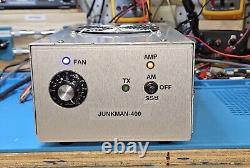
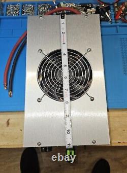
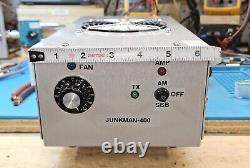
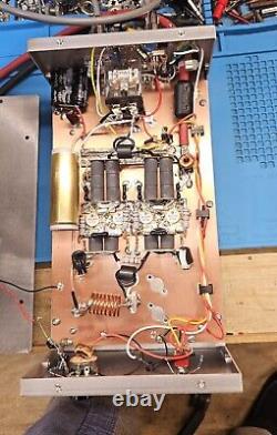
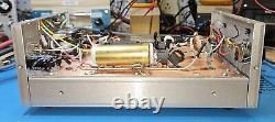
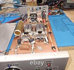
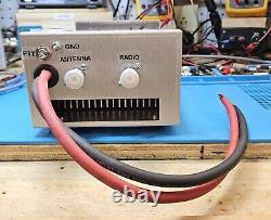

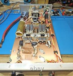
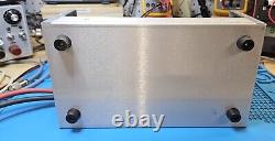
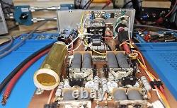
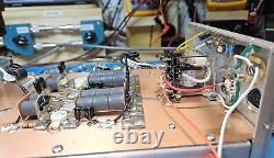
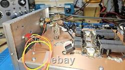
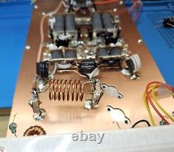
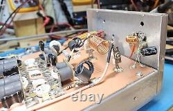


This is a quality-built Ham amplifier to be used on the 10-meter band KG4EBF. I built this amp with 4-2SC2879(100-watt) HG transistors= Junkman-400. The transistors are in the AB class for SSB use.
The test I run on them is at 13.8-VDC with a 200-amp power supply. I use a PNP type keying circuit that is very responsive (will activate relays at less than ½ watt RF power) and will not lock up like the NPN type. The sensitivity of the keying circuit makes it ideal for SSB use.You can also use a foot petal or remote to key the amp from the ¼-inch phono jack marked PTT at the back of the amp. You can also use the keying circuit in this amp to key another amplifier from the ¼ inch phono jack. I use a 10uF 50v electrolytic capacitor for the delay, so your relays do not chatter in SSB mode. All you need to do is put it in SSB mode to talk SSB. You can put up to 70-watts drive into this amplifier.
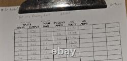
You can see from my test sheet that at 70-watts drive the RF output is 712 watts into a Dummy Load. I use an MFJ-998 and MFJ-815D meter to read RF output power in watts. At 712-watts each transistor is putting out about 175-watts. The 2SC2879 transistor is rated at 100-watts so at 175-watts the transistors are at their ceiling. I wouldn't push them any further.
Of course you can use less drive if you want. That is how to vary the output of this amp is with drive.
I put a 100-ohm potentiometer on the high-velocity fan since you will not need all that fan power. I do not like fan noise, and you will not need the fan to run at full speed because it is noisy, and the amp does not run hot.The cabinets I build these amps in are designed for forced air cooling to keep the amp from overheating at max outputs. I design these amps to be run at max output (700-watts).
I put a protection diode (Schottky 15-amp) on the power strip in case the Linear is hooked up backward with a positive on the negative power cable. Hopefully, the diode with go into a short and prevent damage to the rest of the components.
Once this diode has been shorted it will have to be removed since it will keep blowing fuses. I use an impedance matching device in the input and variable capacitor on the output so the Linear is "tuned". If you notice on the test sheet the swrs are 1.1 at 40-watt drive.
This is the "dip" or where it is tuned it at. When using transistor amplifiers, if you start off with input swrs, they will show up all in your antenna system. I use a T-network (capacitor, inductor, capacitor) which is basically an antenna tuner to match the input of the amp to your radio.
You are matching 50-ohms (most radios are 50-ohms) to the base of 4/2SC2879 transistors which is about 1.5-ohms. After the signal is amplifier it needs to be corrected back to 50-ohms.
Capacitance can adjust this on the output of 2 and 4-pill amps. I use an MFJ-870 swr meter that is very accurate to detect reverse power(swr). This 4-pill design is very durable as I have tweaked it with different resistance, capacitance, and inductance to get the most RF power from the least amount of DC current.
A transistor amplifier is nothing more than converting DC current into RF power. The efficiency comes from the less current in amps for the most RF power in watts otherwise the rest is wasted in heat due to it being out of tune. When a transistor amplifier is out of tune it causes harmonics, false RF power readings, and extra heat. Harmonics are something a radio operator wants to avoid at all costs (your neighbor will love you for this). If you notice the amp will produce 712-watts of RF power with 74-amps at 13.7-vdc current.
That is a good ratio of amps to watts. A transistor amplifier is only as strong as its weakest part.
I find that weak part and replace it with a stronger one. For example, I use an over-sized transistor on the keying circuit. I custom build my own keying circuits. I use 3000-volt capacitor on the output. I use 6-gauge wire instead of 8-gauge on the power cables. 8-gauge wire will not carry 74-amps without getting hot. I use a 30-amp relay.Other builders use 10 and 20-amp. When you switch 700-watt on/off you need good strong contacts that the 30-amp supplies. I use 16-gauge Teflon wire on the transformer windings and other critical connections.
I use 500-volt silver mica capacitors where other builders use 200 volt or disc. I use a metal capacitor instead of disc (a disc capacitor will not carry the load a silver mica or metal will) on the output, 3-watt feedback carbon resistors with 50-volt disc instead of the 2-watt, 25-volt. I use a 5-watt balancing carbon resistor on the output, 3-watt on the input. Detailed hookup directions are included. I also do repair work on both tube and transistor Ham amplifiers. This is just a hobby for me. I have been doing this for 50 years.
